Article No. VK-IND06
IND06 Angle beam testing
Demonstration of the use of ultrasonic angle beam probes for localizing discontinuities
- Subject matter of the experiment
- Theoretical and practical aspects of the experiment
- Results
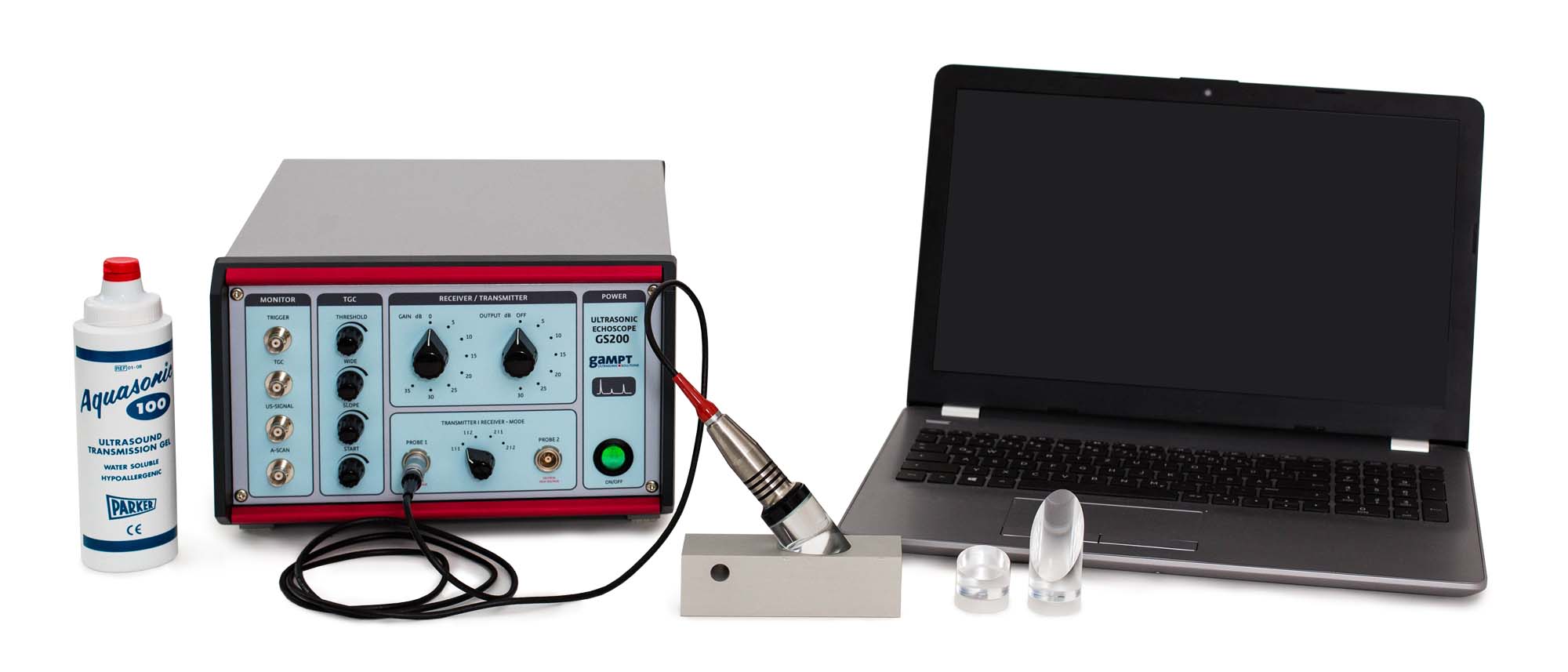
- Equipment
- Related Experiments
The experiment demonstrates the use of ultrasonic angle beam probes for localising discontinuities. Measurements are carried out with delay lines with different angles of incidence, and a delay line is set for the locating of discontinuities in aluminium.
Keywords: Pulse echo method, A-scan, reflection, incidence angle, refraction angle, sound velocity, longitudinal wave, shear wave, refraction, angle echo, skip distance
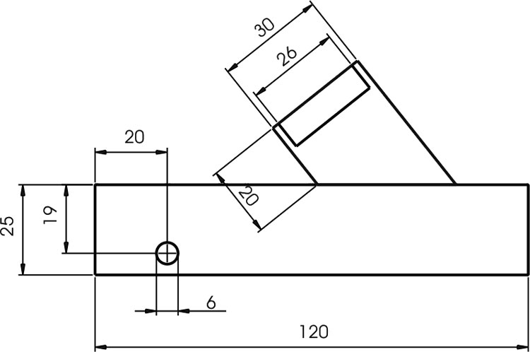
Schematic view of test block and angle beam wedge
Discontinuities often do not run parallel to the surface of the test object, so it is practical or even necessary to pass sound waves through at a specific angle, i.e. investigating with angle beam probes. While the calibration of normal probes for depth measurement only requires the time of flight and sound velocity, in the case of angle beam probes other geometrical factors – such as the incidence angle, the length of the delay line, the sound exit point and the additional exciting of shear waves – must be taken into account due to the oblique sound coupling. Unlike in real practice, in which standardised calibration blocks are used for calibration, in the experiment a simplified test block of aluminium is used. Due to the use of different angle beam wedges in combination with a normal probe, the ultrasonic echoes for different incidence angles can be investigated.
For the 38° and 17° angle beam wedges and the aluminium test block, in a measurement arrangement as schematically presented in the graphic, approximately the following values occur.
| Wave mode | trans. | long. | trans. | Unit |
| Incidence angle | 38 | 17 | 17 | ° |
| Sound exit point | 16,8 | 16,0 | 14,7 | mm |
| Skip distance | 48,9 | 46,0 | 36,8 | mm |
| Refraction angle | 44,5 | 40,7 | 18,5 | ° |
| Sound velocity | 3091,2 | 6436,6 | 3093,2 | m/s |
| Delay line | 18,9 | 13,0 | 12,9 | mm |
| Ord.no. | Description |
|---|---|
| 10400 | Ultrasonic echoscope GS200 |
| 10152 | Ultrasonic probe 2 MHz |
| 10234 | Angle beam wedge 38° |
| 10233 | – optional: angle beam wedge 17° |
| 10235 | – optional: angle beam wedge 56° |
| 10240 | Test block for angle beam probe |
| 70200 | Ultrasonic gel |